AI CAD · CAD StudioDescribe the part. Get the STEP file.
Type what you need — a sample holder, a fixture, a test cell — and attach a sketch if you have one. Butler writes a parametric CAD model, builds it with a real CAD kernel and hands you STEP for the workshop, STL for the 3D printer and a dimensioned 2-D drawing. Need 48 mm instead of 45? Type the number: the part is rebuilt exactly.
100 % on-premise · fully localBuilt for the GDPR — your data never leaves your servers
A brief typed in, the part built, then cut open and measured (build sped up).
How it works
From a sentence to a solid, without a CAD expert.
Behind the text box is a real modelling pipeline: code you can read, a kernel that refuses invalid geometry, and files your CAD software opens as it would its own.
1
Describe it
Dimensions in millimetres, holes, walls, fillets — in plain words. Attach a sketch, a drawing or a photo and its dimensions are read first.
2
Butler writes the model
The language model writes a parametric build123d script in Python, with every dimension a named value at the top.
3
The kernel builds it
OpenCascade builds the solid in an isolated sandbox with no network. If it reports an error, the real message goes back to the model, which repairs the script — up to three times. Then the solid is measured against the sizes the model intended.
4
Download the files
STEP for SolidWorks, Fusion, FreeCAD or Onshape and the CNC mill, STL for the 3D printer, GLB for the web — and the dimensioned drawing as PDF, SVG or DXF.
Built by CAD Studio
Parts for the lab, from a few lines of text.
Every part below was built by CAD Studio from the brief printed under it — no CAD program opened, no sketch drawn.
A tour through the six parts in the 3-D viewer.
Electrochemistry
Three-electrode cell lid
The part built live in the clip above: first try, about ten seconds, a valid solid.
Brief “Lid for a three-electrode electrochemical cell: a 45 mm diameter, 8 mm thick disc. A 6 mm hole in the centre for the working electrode, two 4 mm holes 13 mm from the centre for the counter and reference electrodes, a 2 mm gas purge hole, and a 4 mm deep spigot 38 mm in diameter underneath that fits into the cell beaker.”
Serpentine flow field, manifolds and gasket groove — built in one attempt.
Brief “Bipolar plate for a PEM fuel cell, 100 × 100 × 4 mm: serpentine gas flow field with 1 mm channels, inlet and outlet manifolds, a gasket groove and tie-rod holes.”
The workshop wants a drawing, not a 3-D file. CAD Studio draws one for every part it builds — views, title block and dimensions — ready to print, send or cut.
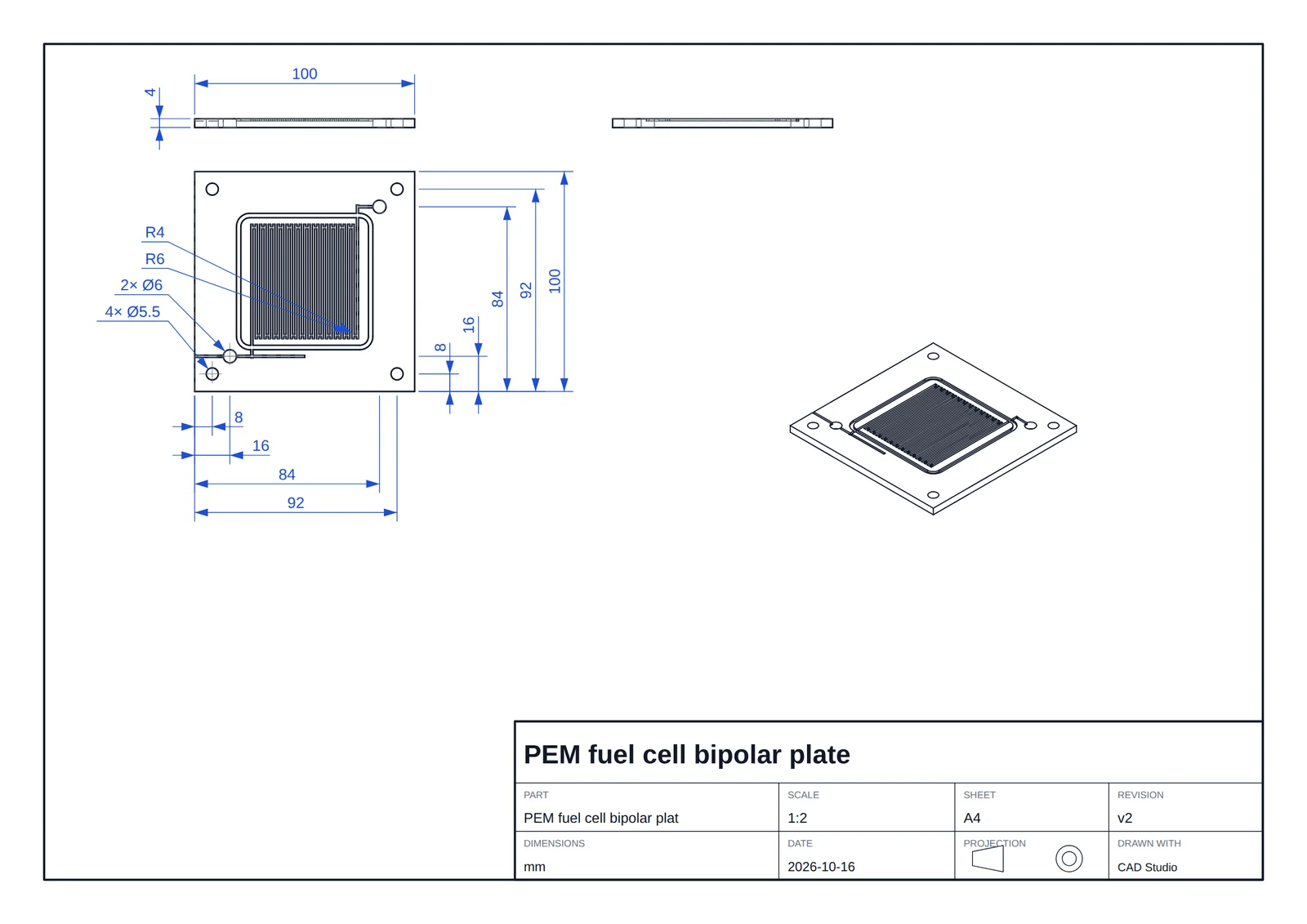
PEM fuel cell bipolar plate — the sheet as CAD Studio generated it.Open full size ↗
An ISO sheet, ready to print
First-angle front, top and side views plus an isometric view on A4 or A3, with a title block: part, scale, sheet size, revision, date and projection symbol. A standard scale — 1:1, 1:2, 2:1 — is chosen for you.
Dimensioned automatically
Overall sizes, hole diameters with their counts (“2× Ø4”), blind-hole depths (“Ø20.4 ↧3.4”), bolt circles (“6× Ø6.6 PCD 58.71”), hole positions and radii — with hidden lines where they help.
PDF, SVG or DXF
PDF to print or send, SVG for documents and the web, and DXF at true size for the workshop, the laser cutter or CAM.
Plain words are fine for a first draft. For the last millimetre you give the value: the part’s named dimensions as number fields, a 2-D plan you can click, and a 3-D view where a click on a face or an edge tells you what it is.
A hole selected and set to Ø 8 mm exactly, then a dimension changed in the 2-D plan — rebuilt each time.
Named dimensions
A tab lists the part’s named measurements — “Lid diameter 45 mm”, “Purge hole diameter 2 mm” — as number fields with their ranges. Change one and the part is rebuilt exactly, in about two seconds, without the AI.
Set LID_D 45 → 48 mm
Click a dimension on the plan
In the 2-D drawing, click a dimension and type the new value. When it is linked to a named measurement, it is set exactly.
Point and edit in 3-D
Click a face or an edge — or two points, to measure the exact distance between them in ΔX, ΔY and ΔZ. Quick actions take an exact value; or type any request, and the selection is sent with it, so the AI designer knows exactly where.
Checked before you see it
The designer states the sizes and holes it intends. Butler measures the real solid and sends any mismatch back for repair before the part reaches you.
The selection says what it is
Hole Ø6Flat face ⟂Z
Quick actions, each with an exact value
Diameter
Depth
Counterbore Ø
Countersink Ø
Through
Move face by
Hole Ø here
Fillet R
Chamfer
Remove
Verified on the cell lid
The lid’s top rim edge selected, and one request typed:
“Fillet R1.5”
“The selected Ø48 top rim edge gets a 1.5 mm fillet instead of the existing 0.5 mm chamfer.” — the designer’s reply, first try.
From the gallery
Or just say what is wrong. The microfluidic chip’s first build came out without its channels; one sentence fixed it:
“the channels are missing…”
Or in plain words
“make the walls 3 mm”
“add a 20 mm centre hole”
“round all outer edges R2”
“two more channels”
Every run a version
Butler edits the model, not a copy of it. Restore any earlier version in one click; failed runs are kept with their error.
Assumptions listed
Whatever you did not specify, Butler chooses — and writes down — so you can check it before manufacturing.
Measured, not guessed
The numbers come from the solid itself.
Every build is measured on the exact B-rep geometry the kernel produced, not on the triangle mesh the viewer draws — the same numbers your CAD software would report.
Size, volume, surface
Bounding box, volume and surface area of the real solid.
Mass and centre of mass
Estimated mass for common materials — PLA, aluminium, steel — and where its centre lies.
Valid solid
A check that the part is a closed, valid solid, before it reaches the printer or the mill.
A viewer that cuts
Iso, top, front and right views, feature edges, a section plane to look inside channels and pockets, and the exact distance between two points (ΔX, ΔY, ΔZ).
Made for labs and workshops
The small parts that hold up the experiment.
Sample holders
Cuvette, wafer and coin-cell holders sized to the sample, printed the same afternoon.
Fixtures and jigs
Clamps, spacers and alignment jigs for the optical table or the test bench.
Test cells and chips
Flow-field plates, microfluidic chips and electrochemical cells as exact STEP for the workshop.
Adapters
Flanges, mounts and brackets that join two things never meant to fit together.
Your designs stay yours
Modelled where your drawings already are.
On your own servers
The model, the CAD kernel and your files run on Butler’s own infrastructure — your descriptions, sketches and parts never leave the institution.
An isolated sandbox
The generated script runs with no network and no file access, and can use only build123d and maths libraries.
Only your parts
Every signed-in user has their own parts; nobody else sees them.
Questions
Which programs open the files?
STEP opens in SolidWorks, Fusion, FreeCAD, Onshape, Inventor and CAM software for the CNC mill; STL goes to any 3D-printing slicer; GLB displays on the web and in AR; the DXF drawing opens in 2-D CAD, laser-cutter and CAM software.
How long does a part take?
From about ten seconds for a simple part, like the cell lid in the recording, to around four minutes for a complex one with many features. Changing a named dimension afterwards rebuilds the part in about two seconds.
Do I get technical drawings?
Yes, for every part: an ISO first-angle sheet with front, top and side views plus an isometric view, a title block, and dimensions placed automatically — overall sizes, holes with their counts and depths, bolt circles, radii. Download it as PDF to print, as SVG, or as DXF at true size for the workshop, the laser cutter or CAM.
Can I set exact dimensions?
Yes. The part’s named dimensions are listed as number fields: change one and the part is rebuilt exactly, in about two seconds, without the AI. You can also click a dimension in the 2-D plan, or select a face or an edge in 3-D and give it an exact value — a diameter, a depth, a fillet radius.
Do I need to know CAD or Python?
No. You describe the part in words, with its dimensions in millimetres. The Python model is generated for you, with every dimension a named value.
Can I trust the dimensions?
The measurements are exact for the solid that was built. Butler checks that solid against the sizes and holes the designer intended and sends any mismatch back for repair, and every value it had to assume is listed. The design itself comes from a language model: check critical dimensions and tolerances before production.
What works best?
Prismatic parts — plates, holders, brackets, housings, channels and hole patterns. Threads, gears and organic shapes are possible but less reliable; describe them step by step.
Can I start from a drawing?
Yes: attach a sketch, a drawing or a photo. A vision model reads its dimensions first, and anything it only estimates is treated as an assumption.
Bring us the part you need next.
Tell us what your lab needs printed or machined — we build it with you in CAD Studio, live.